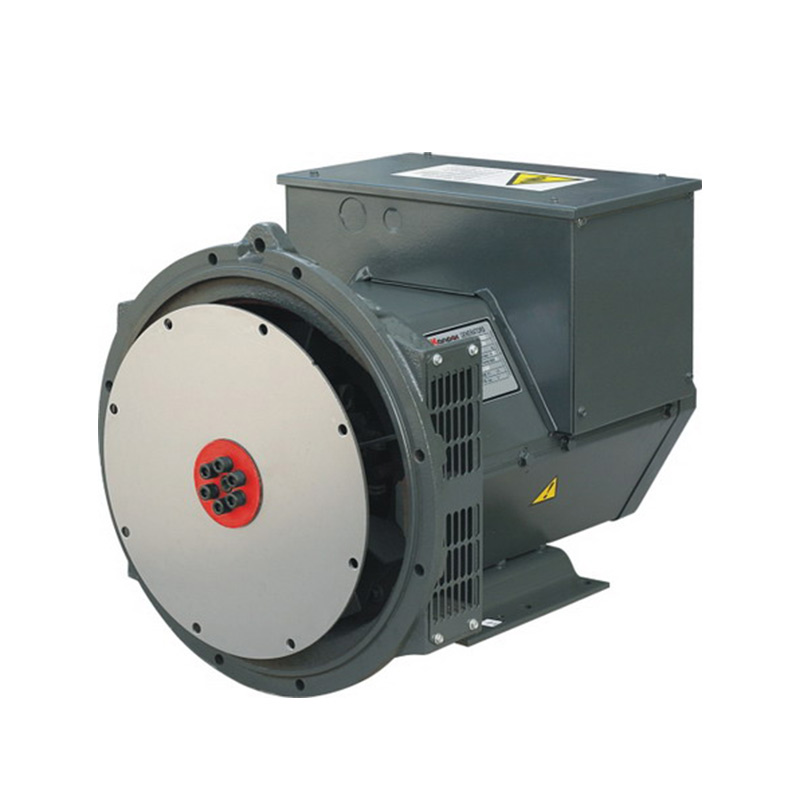
Matching a prime mover to its electrical end carries immense stakes for any facility. You need absolute precision to keep critical systems running smoothly. Unfortunately, many buyers make a crucial error during procurement. They strictly match engine horsepower to their baseline electrical load. They often ignore heat dissipation, non-linear harmonics, and variable application duty cycles. Miscalculating your generator alternator capacity does not just trigger minor inefficiencies. It quickly leads to severe thermal degradation, tripped breakers during transient loads, and highly expensive downtime. We will outline the exact technical framework you need to successfully pair engines and alternators. You will learn how to navigate complex thermal ratings, choose proper excitation systems, and assess diverse load profiles. Read on to master these principles and ensure reliable, compliance-driven equipment selection for your next power project.
Key Takeaways
Engine mechanical output (kW) and alternator electrical output (kVA) must be aligned based on specific duty cycles (ISO 8528-1 ratings) rather than peak theoretical numbers.
Blindly over-sizing an alternator for UPS compatibility is an outdated, expensive practice; selecting the right excitation method (like PMG) solves voltage distortion more effectively.
Alternator lifespan is fundamentally dictated by thermal management; operating below the maximum insulation temperature class significantly extends equipment life.
1. Defining Baseline Load and Generator Alternator Capacity
You cannot effectively pair an engine and an alternator using peak theoretical numbers alone. To build a reliable system, you must first assess the specific duty cycle. The ISO 8528-1 standard defines three primary operational categories. These include Emergency Standby Power (ESP), Prime Power (PRP), and Continuous Operating Power (COP). Each category demands a unique approach to capacity planning.
Consider a hospital standby unit. It typically runs fewer than 200 hours annually. This infrequent usage allows you to utilize higher peak capacity ratings safely. The equipment cools down fully between operations. Conversely, a prime power unit might run up to 8,000 hours per year. This continuous operation requires strict capacity derating. You cannot push an alternator to its peak limit indefinitely without causing massive thermal failure.
Sizing by Application Tier
Different application tiers introduce distinct power generation demands. You must categorize your site requirements carefully.
Light Commercial and Telecom: These sites often rely on an 8-40kVA alternator. Variable loads and rapid deployment capabilities are prioritized here. The equipment must respond instantly to grid failures.
Industrial and Heavy Commercial: Large manufacturing plants typically specify a 250-750kVA alternator. Heavy commercial sites demand exceptional phase balancing. Fault clearing and sustained motor-starting capabilities remain critical at this tier.
The Sizing Formula
Calculating the correct baseline requires precise math. You must follow standard AC alternator sizing principles. Begin by dividing your total watts by the system voltage. This gives you the fundamental amperage requirement. However, stopping at this baseline is a common mistake. You must build in a strict 30% to 40% operational margin. This margin accounts for system efficiency degradation over time. It also absorbs sudden inrush currents from large motor starts. Skipping this buffer forces your system to run near 100% load continuously, drastically shortening its lifespan.
2. Navigating Thermal Limits and Insulation Classes
Heat is the primary enemy of electrical equipment. Continuous electrical output is strictly limited by a physical bottleneck: heat dissipation capacity. This principle follows the formula P=I⊃2;R. As current flows through the internal windings, resistance generates intense heat. You must regulate this output carefully. If you fail to do so, internal windings will rapidly exceed their thermal limits, causing catastrophic insulation failure.
Insulation Specifications
Industry standards classify internal insulation based on strict temperature rise limits. You must select the right class to guarantee operational longevity.
Insulation Class
Max Temp Limit
Primary Application
Key Characteristics
Class H
180°C
Low-Voltage / Standby
Industry standard for compact footprint. Runs hotter.
Class F
155°C
Medium/High-Voltage
Excellent balance of heat management and size.
Class B
130°C
Continuous Prime
Maximizes winding lifespan up to 120,000 hours.
Class H insulation stands as the industry standard for low-voltage systems. It allows manufacturers to build a much more compact footprint. However, the equipment inherently operates at hotter temperatures. This makes Class H ideal for intermittent standby applications. In contrast, medium-to-high voltage systems demand Class F or Class B insulation. Prime continuous applications rely heavily on these cooler operating classes. By capping the temperature limit lower, you maximize the winding lifespan. This enables up to 120,000-hour operational lifecycles.
Risk Mitigation
Running a Class H insulated alternator at its thermal ceiling for prolonged periods carries severe risks. High temperatures accelerate material degradation. You should actively avoid pushing the system to 180°C continuously. Derating the alternator for continuous use represents a structural necessity, not an optional upgrade. Oversizing the thermal rating slightly guarantees the winding insulation remains intact over decades of heavy use.
3. Managing Non-Linear Loads: The UPS Compatibility Myth
Facilities heavily reliant on digital infrastructure often pair backup power with Uninterruptible Power Supply (UPS) systems. Unfortunately, a massive misunderstanding plagues this integration. The industry frequently promotes the "over-sizing" fallacy. Conventional wisdom claims you must size a generator alternator two to five times larger than the connected UPS system. Engineers mistakenly believe this prevents catastrophic electrical faults. This practice wastes massive capital expenditure and fails to address the root technical issue.
Understanding Voltage Distortion
UPS systems operate as non-linear loads. They draw current in abrupt pulses rather than smooth waves. This pulsing causes severe voltage wave notching. Standard Automatic Voltage Regulators (AVRs) rely heavily on zero-crossing detection to monitor power flow. When a UPS notches the waveform, it creates false zero-crossings. The standard AVR becomes confused and triggers erratic voltage adjustments. This results in unstable power delivery across the facility.
Control Loop Conflicts
The problems extend beyond simple wave distortion. Generators experience rapid frequency slew rates during sudden load acceptance. Fluctuations can hit speeds of 10 to 15 Hz per second. The generator governor aggressively tries to correct this frequency drop. Simultaneously, the UPS detects the drop and adjusts its own input parameters. This creates a dangerous negative feedback loop. The two control systems actively fight each other, often causing the UPS to drop the load entirely.
Engineering Fixes
You can solve these conflicts without buying massively oversized equipment. We recommend integrating a 10% resistive base load into your system architecture. This linear base load smooths out the wave notching. It acts as an electrical anchor, stabilizing rapid frequency fluctuations. This simple engineering fix prevents UPS dropouts effectively. It keeps your facility online without demanding exorbitant upfront investments in oversized machinery.
4. Selecting the Right Excitation System for Your Sizing Strategy
Excitation systems supply direct current to the spinning rotor. This current creates the magnetic field necessary to generate electricity. The specific excitation method you choose directly dictates performance. It governs the alternator’s ability to handle heavy transient loads and clear short circuits safely. If you pick the wrong system, your facility risks sudden power collapse during emergencies.
Evaluating Excitation Options
You generally have three distinct excitation options to evaluate during procurement.
Shunt Systems: This remains the most cost-effective solution. The system draws power directly from the main stator. However, it carries severe limitations. Shunt setups are highly prone to sudden voltage collapse during severe short circuits.
Auxiliary Winding: This mid-tier solution provides a completely separate power source for the AVR. It offers highly robust short-circuit protection. An auxiliary system can easily sustain three times the rated current for up to 10 seconds.
Permanent Magnet Generator (PMG): PMG stands as the undisputed enterprise standard for non-linear loads. It completely isolates the AVR power supply. Voltage distortions caused by heavy facility loads cannot interfere with AVR performance.
Decision Criteria
You must link your choice of excitation to the facility's specific risk profile. Evaluate your fault-clearing requirements thoroughly. If your site features heavy motor-starting demands or complex UPS networks, avoid shunt systems. Invest in Auxiliary Winding or PMG setups instead. The upfront premium guarantees system resilience when grid failures occur. PMG systems guarantee that your voltage regulation remains rock-solid, regardless of the chaos happening downstream.
5. Evaluation Framework: Finalizing the Power Generation Alternator Spec
Finalizing your equipment specification requires moving beyond basic kVA numbers. You must architect the entire electrical end to match your facility. This process involves examining connection configurations, internal winding designs, and environmental defenses.
System Architecture Matching
Commercial deployments demand high flexibility. You should ensure 12-wire connection configurations are specified in your procurement documents. A 12-wire setup allows for maximum reconnection flexibility. You can easily switch between Star and Delta configurations. This adaptability proves invaluable if facility voltage requirements change years after the initial installation.
Winding Pitch Selection
Internal winding geometry plays a massive role in system efficiency. We highly recommend specifying a 2/3 winding pitch for low-voltage systems. Non-linear loads produce harmful 3rd harmonics. These harmonics travel down the neutral wire and generate extreme heat. A 2/3 winding pitch effectively cancels out these 3rd harmonics. It directly prevents dangerous neutral heating, preserving the usable capacity of your machine.
Environmental Resiliency Checks
Ambient conditions dictate real-world performance. You must detail necessary upgrades for harsh environments. Coastal sites require marine-grade epoxy coatings to fight aggressive salt corrosion. Humid environments demand anti-condensation heaters. These heaters prevent moisture buildup inside the windings while the unit sits idle. Failing to implement these physical defenses leads to rapid capacity degradation.
Shortlisting Actions
Instruct your procurement teams to look past top-line marketing numbers. Request specific derating curves and short-circuit decrement curves from every vendor. These engineering documents reveal exactly how a power generation alternator performs under stress. Compare these curves against your actual site data. This rigorous verification process eliminates undersized equipment before the purchase order is even drafted.
Conclusion
Effective equipment pairing requires balancing mechanical engine power with strict thermal realities and advanced excitation capabilities. You cannot simply read a kVA nameplate and assume the system will handle your specific facility demands. Insulation limits, voltage distortions, and harsh environments all constrain your true operational capacity. Precision engineering prevents thermal failures and guarantees reliable backup power.
Always audit your site load profiles carefully. Map out the exact ratio of linear to non-linear loads. Determine whether your application demands standby or prime continuous operation. Finally, demand detailed decrement curves from manufacturers before requesting formal RFQs. Taking these deliberate steps ensures your next procurement cycle delivers a highly resilient, compliance-ready power system.
FAQ
Q: Why is engine horsepower rating usually different from alternator kVA rating?
A: Engine horsepower represents mechanical output, while alternator kVA represents apparent electrical power. Converting between them requires factoring in the alternator's internal electrical efficiency and the system's power factor. Because alternators inherently lose some energy as heat, the electrical kVA rating will always differ from the raw mechanical horsepower input.
Q: Can I rely purely on nameplate amperage for continuous output?
A: No. Nameplate amperage usually reflects a peak testing condition under controlled lab environments. Your continuous safe capacity is heavily dictated by your specific ambient site temperature and internal insulation class limits. You must apply a derating factor if you plan to run the equipment continuously.
Q: Does winding pitch affect my alternator's capacity?
A: Yes. Winding pitch design directly minimizes internal harmonic distortion. A 2/3 pitch blocks 3rd harmonics from circulating through the neutral wire. This reduction in wasted heat preserves internal thermal headroom, effectively maximizing the usable capacity available for your actual facility loads.
DONGCHAI POWER devotes itself to manufacuring and maintenance of different types generator, diesel generator, gas generator, silent generator, reefer generator, container generator and sychronization generator.